
Non-thermal cutting helps preserve the properties that made the material valuable.
Finecut flagship platform
WMC
500II.
One compact, fully encapsulated precision platform. Six standard motion concepts. Configure the machine around flat profiles, rotating parts, taper-free production or complex 3D geometry.
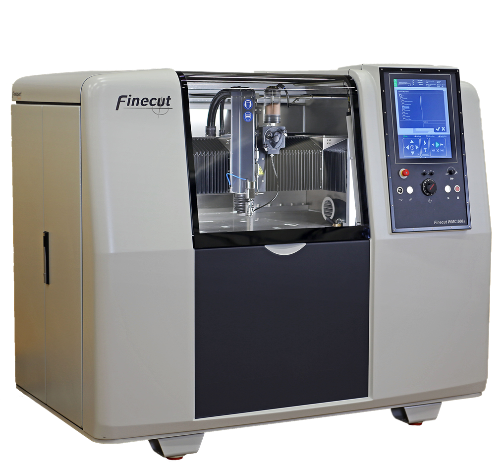 WMC500II
3X cutting envelope
500 × 500 × 80 mm
Positioning accuracy
±1.5 µm
Maximum traverse
40 m/min
Typical part tolerance
down to ±10 µm
Included system scope
WMC500II is the core.
The system completes it.
Every Finecut System brings together the precision machine tool, ultra-high-pressure pump, water treatment, workspace ventilation and the software needed to program the process.
See what a Finecut System includes ↗Why WMC500II
Precision without
process compromise.
The WMC500II cuts cold, so the material is not distorted by a heat-affected zone. Its rigid machine-tool architecture, high-resolution feedback and application-specific control create a productive route to intricate parts in metals, composites, glass, ceramics and polymers.
Pierce and cut in one setup, with minimal cutting force and a narrow kerf.
Hardware and capability options are designed to be retrofittable across the WMC500II series.
Technical specifications
Machine-tool precision.
Finecut flexibility.
Core specifications for a newly produced Finecut WMC500II in standard 3-axis configuration. Multi-axis working envelopes and performance depend on the selected motion concept, fixture, cutting head and application.
- CNC
- FANUC 31i-B5 with ALPHA servo drive and Nano Control
- X / Y motion
- Linear servo motors
- Z motion
- Precision ball screw servo
- Position feedback
- Thermally stable Invar absolute linear encoders, 50 nm resolution
- Maximum cutting speed
- 20 m/min
- Maximum traverse speed
- 40 m/min
- X / Y acceleration
- 0.5 g
- Positioning accuracy
- ±1.5 µm according to ISO 230-2
- Repeatability
- ±1.5 µm according to ISO 230-2
- 3X cutting envelope
- 500 × 500 × 80 mm
- Fixturing area
- 700 × 700 mm, maximum depth 700 mm
- Machine table
- 900 × 900 mm (W × D)
- Typical finished-part tolerance
- Down to ±10 µm in suitable applications
Fine abrasive waterjet cutting systems
Jet power and high-pressure water consumption are stated at 4,000 bar. The final cutting system is selected for the material, thickness, geometry and production target.
| Cutting system | Jet diameter | Jet power | HP water |
|---|---|---|---|
| FAW200 | 0.2 mm | 2.3 kW | 0.2 L/min |
| FAW300 | 0.3 mm | 5.6 kW | 0.4 L/min |
| FAW400 | 0.4 mm | 11.7 kW | 0.9 L/min |
| FAW500 | 0.5 mm | 14.6 kW | 1.2 L/min |
| PWJ, non-abrasive | 0.08–0.25 mm | Application dependent | |
Important: Positioning accuracy and repeatability describe machine motion under the stated test standard. They are not guaranteed finished-part tolerances. Achievable part accuracy, kerf and surface finish must be qualified for the material, thickness, geometry, cutting parameters and machine configuration.
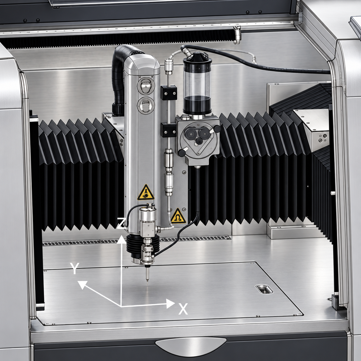
01 · Finecut 3X
Flat precision
Ultra-precise 2D contours and repeatable production with coordinated X, Y and Z motion.
500 × 500 × 80 mm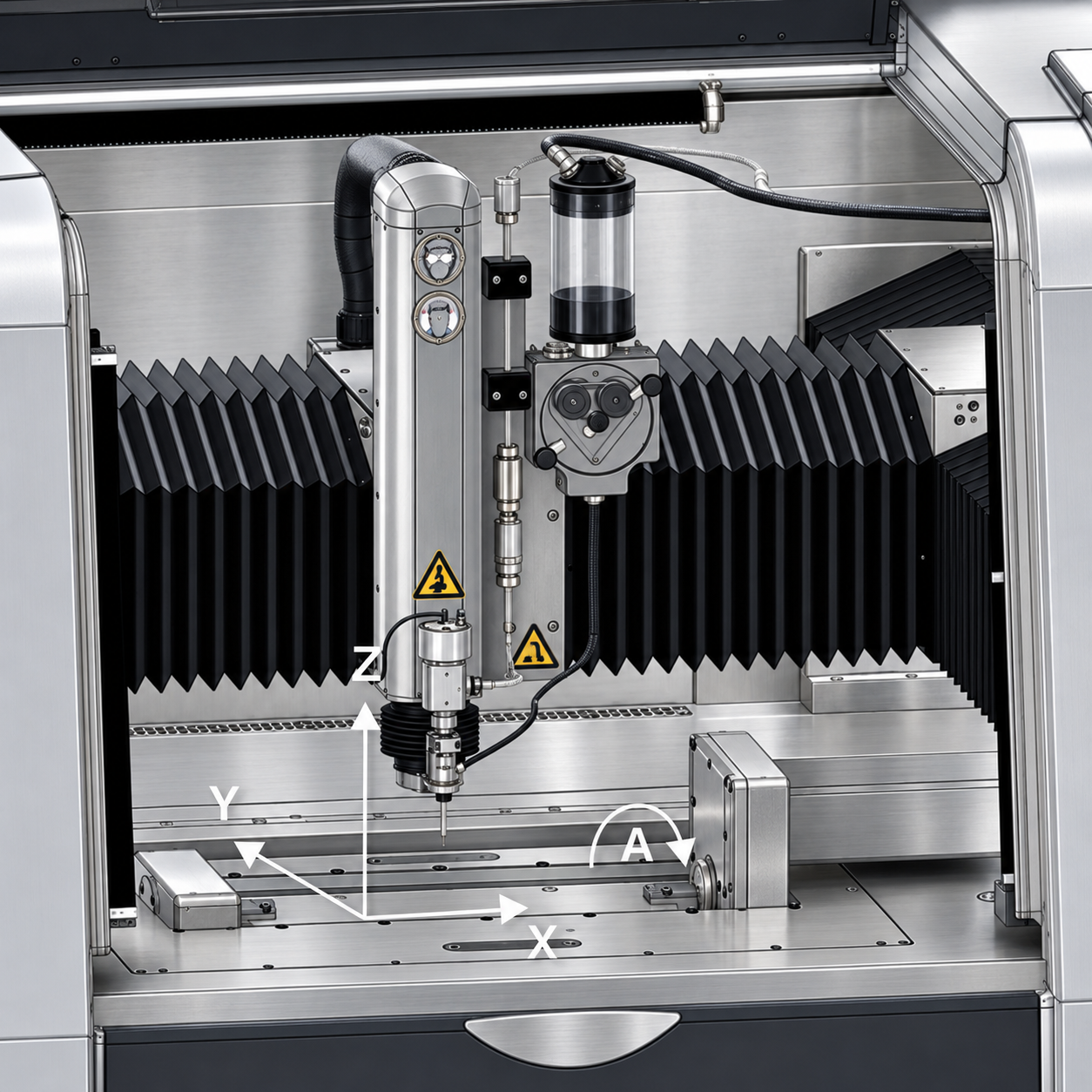
02 · Finecut 4X, type A
Rotate the workpiece
A detachable table-mounted A-axis rotates the workpiece synchronously for tubes, rotational contours and multi-side access.
A-axis · 360°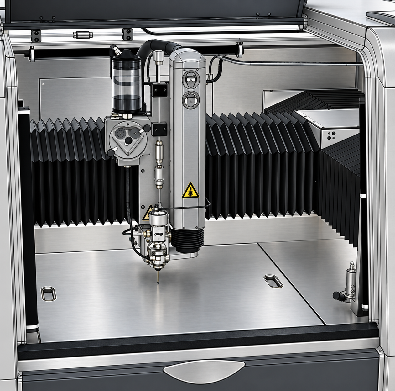
03 · Finecut 4X, type B
Tilt the jet
A tiltable B-axis complements 3-axis precision for uni-directional chamfers, relief angles and angled edges.
B-axis · ±45°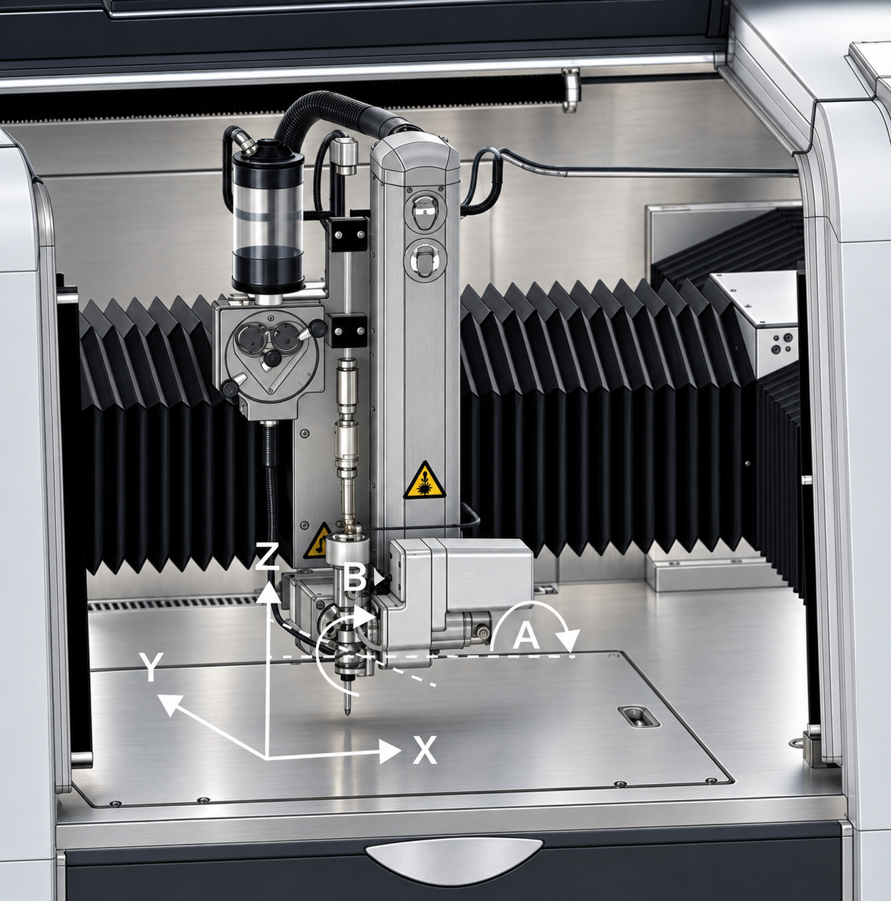
04 · Finecut 5X, type ABX
Control taper
Synchronous A- and B-axis head motion with TCP control for taper compensation, bevels and 3D cutting.
A/B · ±15°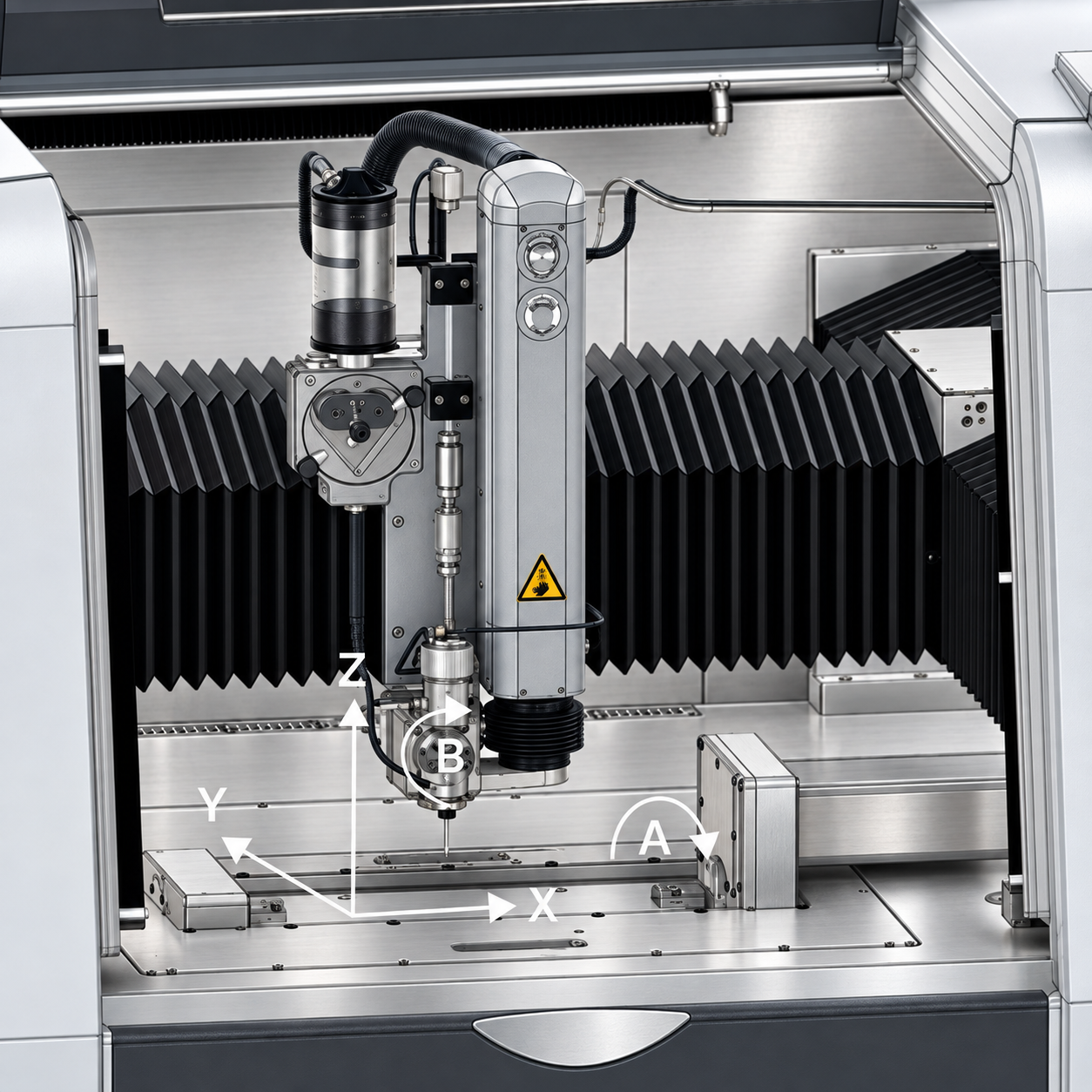
05 · Finecut 5X, type B4X
Complex 3D access
Combines a tilting cutting system with workpiece rotation for complex geometries and multi-side machining.
B ±45° · A ±360°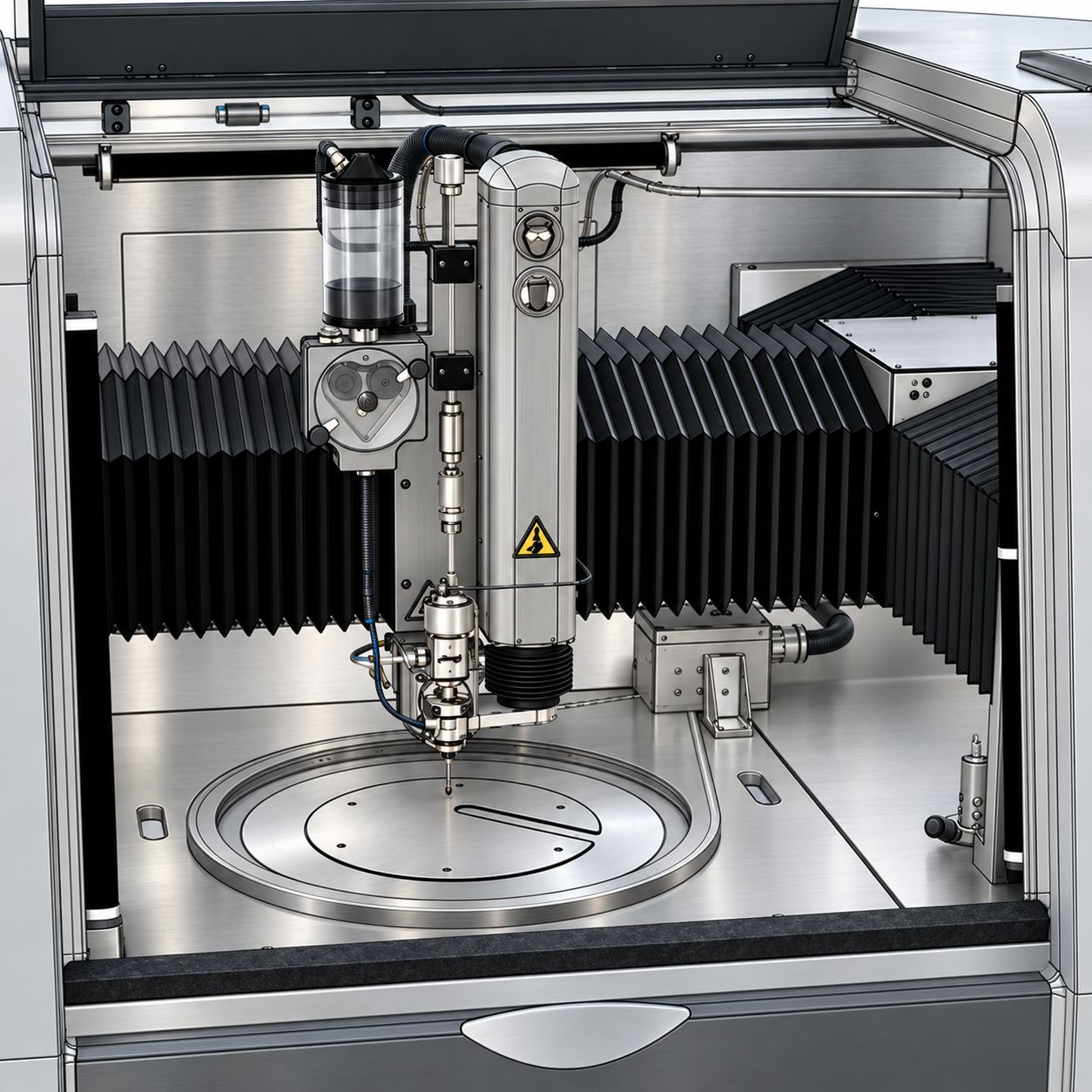
06 · Finecut 5X, type CBX
Dynamic contour bevels
A C-axis rotary table works with the tilting B-axis to create synchronized angled contours and special taper geometries.
B ±45° · C unlimited 360° Request technical specification ↗Configuration-specific technical comparison
Values are stated as positioning accuracy / repeatability. Every configuration retains full 3-axis capability at ±1.5 / ±1.5 µm. Multi-axis results marked application-dependent must be qualified for the material, thickness, geometry, fixture and cutting strategy.
| Configuration | Working envelope | Axes / angular range | Motion concept | Positioning / repeatability | Finished-part tolerance | Typical applications |
|---|---|---|---|---|---|---|
| 3X | 500 × 500 × 80 mm | X, Y, Z | Fixed workpiece; vertical jet | 3X: ±1.5 / ±1.5 µm | Down to ±10 µm | Flat precision components, 2D contours and series production |
| 4X, type A | 500 × 500 × 80 mm; tilt table approx. 350 × 180 mm | X, Y, Z + A; A unlimited 360° | Detachable table-mounted A-axis rotates the workpiece | 3X: ±1.5 / ±1.5 µm; with A: ±2.5 / ±2.0 µm | 3X down to ±10 µm; multi-axis application-dependent | Tubes, cylindrical and helical features, multiple sides |
| 4X, type B | 500 × 500 × 80 mm | X, Y, Z + B; B ±45° | B-axis tilts the nozzle in one direction | 3X: ±1.5 / ±1.5 µm; with B: ±2.5 / ±2.0 µm | 3X down to ±10 µm; multi-axis application-dependent | Angles, bevels and taper compensation in one axis |
| 5X, type ABX | 500 × 500 × 80 mm | X, Y, Z + A, B; A/B ±15° | Two rotary axes tilt the nozzle in any direction | 3X: ±1.5 / ±1.5 µm; multi-axis not universally specified | 3X down to ±10 µm; 5-axis down to ±25 µm | Active taper compensation, controlled angles and productivity |
| 5X, type B4X | 500 × 500 × 80 mm; tilt table approx. 350 × 180 mm | X, Y, Z + B + A; B ±45°, A 360° | B-axis tilts the nozzle; detachable A-axis rotates the workpiece | 3X: ±1.5 / ±1.5 µm; additional axes: ±2.5 / ±2.0 µm | 3X down to ±10 µm; multi-axis application-dependent | Complex 3D parts, tubes, helices and multiple sides |
| 5X, type CBX | 500 × 500 × 80 mm; up to approx. Ø350 mm at full B tilt | X, Y, Z + B + C; B ±45°, C unlimited 360° | B-axis tilts the nozzle; table-mounted C-axis rotates the workpiece | 3X: ±1.5 / ±1.5 µm; multi-axis not universally specified | 3X down to ±10 µm; multi-axis not universally specified | Discs, rotational symmetry and advanced 3D work |
Positioning accuracy and finished-component tolerance are separate specifications. The values above are based on FP-MS-260118, v00.
Final capability, tolerance and retrofit compatibility depend on machine configuration, material, geometry, process setup and local requirements.
Best fit
Built for the work
other processes avoid.
Preserve critical properties in aerospace alloys, composites and heat-sensitive materials.
Defence · aerospace · energyReach intricate geometries in glass, technical ceramics and other brittle materials.
Photonics · electronics · researchCombine digital geometry, flexible fixturing and stable motion in one compact cell.
Medical · precision engineeringProve it before you invest
Your drawing.
Our test cut.
Let Finepart evaluate material, geometry, tolerance and production target—and recommend the right WMC500II configuration.
Request a test cut ↗